| Version 5 (modified by , 13 years ago) ( diff ) |
|---|
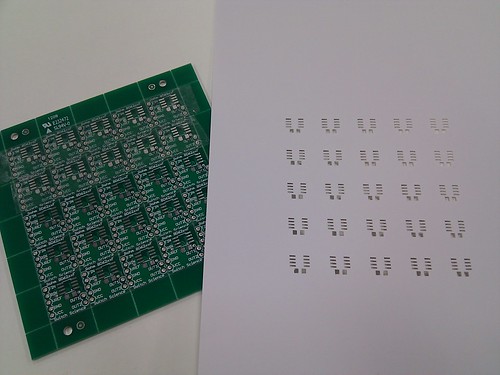
EAGLEで作った基板のハンダマスクをCraft ROBOで作る
表面実装用の、ハンダマスクっていうか、Solder Stencilっていうか。 Craft ROBOでお手軽に作っちゃおうという魂胆です。 Craft ROBOの専用ソフトROBO Masterには、DXFを読み込む機能があります。 じゃ、EAGLEからDXFを吐き出せばOKじゃん!って思いましたが、うまくいきません。 EAGLEに付属のdxf.ulpで出力したDXFファイルをROBO Masterに読み込ませると、「有効なデータがありません」とか怒られます。 いろいろ悩んで設定を試してみましたが、どうしてもうまくいかないので、スクリプトを自分で作ることにしました。
DXFのフォーマットは変態だし、ULPをいじったのは初めてだしで、ちょっと悩みましたが、とりあえず動いています。 近々、実際にカットしてみます。うまくいくといいんですが。 サポートしているのは、tCream/bCreamレイヤに有るパッドのうち、四角の物だけです。 パッドの角を丸めてあっても、四角として扱います。 その他の図形は、存在しても出力しません。
パネライズが必要な場合は、事前にEAGLEの上で手作業で行うといいでしょう。 基板の外形やトンボなどは、全く出力しません。 目で基板と合わせてください。 ROBO MasterでDXFを読み込んだだけでは、原点=左下角近くに配置されています。 クリームはんだの印刷の都合を考えると、シートの真ん中辺りに配置して有る方がいいと思います。 読み込んだあとに、手作業で移動させてください。
Make a solder stencil using the "Craft ROBO" cutting plotter
Here is an EAGLE ulp script to produce DXF files for tCream and bCream layers. Just copy and paste to a file named "cream-dxf.ulp", and drop in the EAGLE ulp directory. In the board window, type "run cream-dxf" and enter key. "board-tcream.dxf" and "board-bcream.dxf" will appear in the directory whre "board.brd" is. You can import these DXF files in the "Craft ROBO" support software ("ROBO Master").
Limitation: Only rectangle SMD pads are supported. "Roundness" parameter is just ignored.
EAGLE provides "dxf.ulp", but this will not produce a correct DXF file for cream layers.
cream-dxf.ulp:
//
// Export the cream layers to DXF for the Craft-ROBO cutting machine.
//
// Copyright (c) 2010 Switch Science, Inc.
//

string HEADER =
"  0\n"
"SECTION\n"
"  2\n"
"HEADER\n"
"  9\n"
"$ACADVER\n"
"  1\n"
"AC1014\n"
"  9\n"
"$HANDSEED\n"
"  5\n"
"FFFF\n"
"  9\n"
"$MEASUREMENT\n"
" 70\n"
"     1\n"                              // unit: mm
"  0\n"
"ENDSEC\n"
"  0\n"
"SECTION\n"
"  2\n"
"ENTITIES\n";

string POLYLINE =
"  0\n"
"LWPOLYLINE\n"
"  5\n"
"%d\n"                                  // id
"100\n"
"AcDbEntity\n"
"  8\n"
"0\n"
" 62\n"
"7\n"
"100\n"
"AcDbPolyline\n"
" 90\n"
"%d\n"                                  // number of points
" 70\n"
"0\n";

string POINT =
" 10\n"
"%f\n"
" 20\n"
"%f\n"
" 30\n"
"0.0\n";

string TRAILER =
"  0\n"
"ENDSEC\n"
"  0\n"
"EOF\n";

void processLayer(UL_BOARD B, int layer) {
  int cream = (layer == LAYER_TOP ? LAYER_TCREAM : LAYER_BCREAM);
  int id = 100;
  printf("%s", HEADER);
  B.elements(E) {
    E.package.contacts(C) {
      if (C.smd && C.smd.layer == layer) {
        real x = C.smd.x / 10000.0;
        real y = C.smd.y / 10000.0;
        real w = C.smd.dx[cream] / 10000.0 / 2;
        real h = C.smd.dy[cream] / 10000.0 / 2;
        real a = C.smd.angle / 180 * PI;
        real wc = w * cos(a);
        real hs = h * sin(a);
        real ws = w * sin(a);
        real hc = h * cos(a);
        printf(POLYLINE, id++, 5);      // 5 points
        printf(POINT, x + wc - hs, y + ws + hc);
        printf(POINT, x - wc - hs, y - ws + hc);
        printf(POINT, x - wc + hs, y - ws - hc);
        printf(POINT, x + wc + hs, y + ws - hc);
        printf(POINT, x + wc - hs, y + ws + hc);
      }
    }
  }
  printf("%s", TRAILER);
}

board(B) {
  output(filesetext(B.name, "-tcream.dxf")) processLayer(B, LAYER_TOP);
  output(filesetext(B.name, "-bcream.dxf")) processLayer(B, LAYER_BOTTOM);
}
(2010/11/11 - sgk)