コテ先温度計シールドの使い方
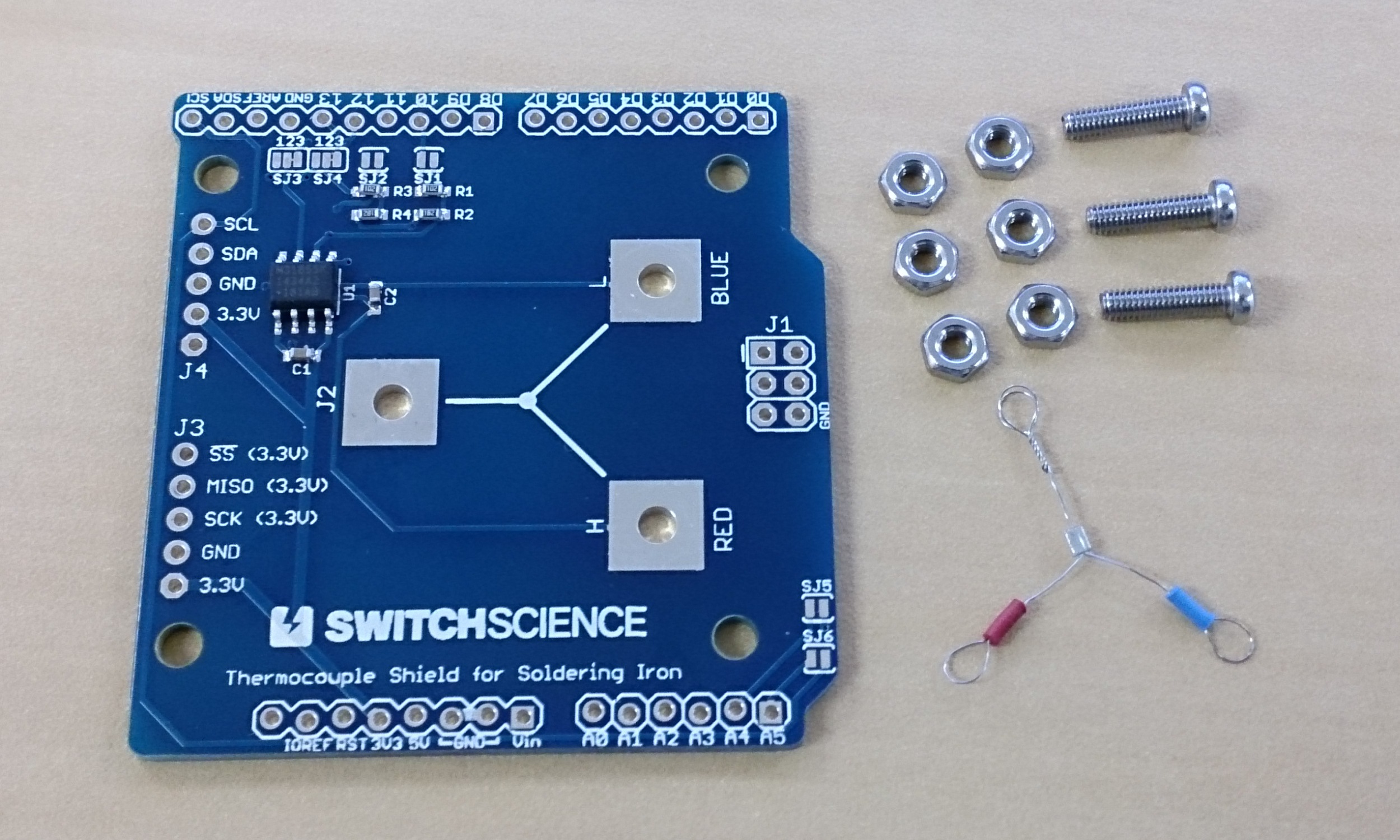
コテ先温度計シールド には基板の他に次の物が入っています。
- M2.6x10 ステンレスナベネジ 3本
- M2.6 ステンレスナット 6個
- HAKKO 191-212 熱電対 2個 (1つは予備)

組み立て
【1】
Arduino用シールドとして使用する場合はまずピンヘッダを実装して、Arduinoに接続できるようにします。(以降の組み立て説明の写真ではピンヘッダを省略しています。)
(ピンヘッダはコテ先温度計シールドには付属しません。)
シールドとして使わない場合J3を利用して別のマイコンと接続することもできます。
【2】
ネジを3本通して、ナット二つで固定します。

【3】
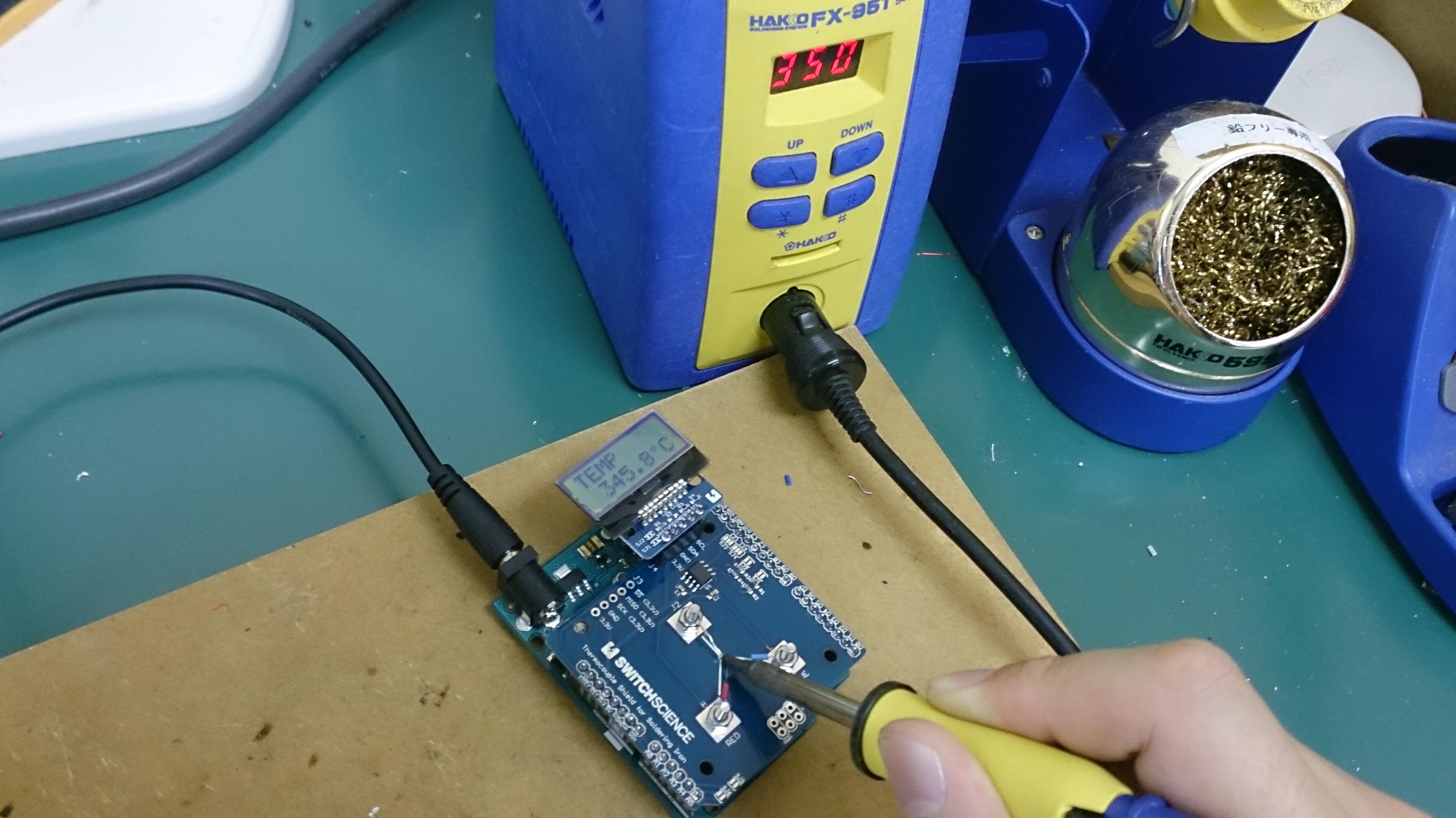
熱電対の赤と青の端子を基板の文字に合わせてネジに通します。一番最後にあまった端子をネジに通します。

これで組み立ては完成です。
基本設定
Arduino Uno R3でコテ先温度計シールドを使用する場合特に変更は必要ありません。
Arduino Leonardo等のSPI端子がICSP端子から出ているArduinoの場合にはショートジャンパSJ3とSJ4の2-3をカットして1-2を接続する必要があります。
Arduino M0 proやArduino YúnのようにI/Oの電圧が3.3VのArduinoの場合はSJ1とSJ2をそれぞれショートさせる必要があります。
サンプルスケッチ
#include <Wire.h>
#include <SPI.h>

#define SLAVE 10
#define sdaPin 18    // ArduinoA4
#define sclPin 19    // ArduinoA5
#define I2Cadr 0x3e  // 固定
byte contrast = 35;  // コントラスト(0~63)
char unit[3] = {0xF2,'C',0};

void setup() {
  pinMode(SLAVE, OUTPUT);
  digitalWrite(SLAVE, HIGH);

  Serial.begin(9600);
  SPI.begin();
  SPI.setBitOrder(MSBFIRST);
  SPI.setClockDivider(SPI_CLOCK_DIV4);
  SPI.setDataMode(SPI_MODE0);


  Wire.begin();
  lcd_cmd(0b00111000); // function set
  lcd_cmd(0b00111001); // function set
  lcd_cmd(0b00000100); // EntryModeSet
  lcd_cmd(0b00010100); // interval osc
  lcd_cmd(0b01110000 | (contrast & 0xF)); // contrast Low
  lcd_cmd(0b01011100 | ((contrast >> 4) & 0x3)); // contast High/icon/power
  lcd_cmd(0b01101100); // follower control
  delay(200);
  lcd_cmd(0b00111000); // function set
  lcd_cmd(0b00001100); // Display On
  lcd_cmd(0b00000001); // Clear Display
  delay(2);


}

void loop() {
  unsigned int thermocouple; // 14-Bit Thermocouple Temperature Data + 2-Bit
  unsigned int internal; // 12-Bit Internal Temperature Data + 4-Bit
  float disp; // display value
  delay(500);
  lcd_clear();
  lcd_setCursor(0,0);
  lcd_printStr("TEMP");
  lcd_setCursor(0,1);

  digitalWrite(SLAVE, LOW);                             //  Enable the chip
  thermocouple = (unsigned int)SPI.transfer(0x00) << 8;   //  Read high byte thermocouple
  thermocouple |= (unsigned int)SPI.transfer(0x00);       //  Read low byte thermocouple
  internal = (unsigned int)SPI.transfer(0x00) << 8;       //  Read high byte internal
  internal |= (unsigned int)SPI.transfer(0x00);           //  Read low byte internal
  digitalWrite(SLAVE, HIGH);                            //  Disable the chip

  if((thermocouple & 0x0001) != 0) {
    Serial.print("ERROR: ");
    if ((internal & 0x0004) !=0) {
      Serial.print("Short to Vcc, ");
      lcd_printStr("Short Vc");
    }
    if ((internal & 0x0002) !=0) {
      Serial.print("Short to GND, ");
      lcd_printStr("Short G");
    }
    if ((internal & 0x0001) !=0) {
      Serial.print("Open Circuit, ");
      lcd_printStr("Open");
    }
    Serial.println();
  } else {
    if((thermocouple & 0x8000) == 0){ // 0℃以上   above 0 Degrees Celsius
      disp = (thermocouple >> 2) * 0.25;
    } else {                          // 0℃未満   below zero
      disp = (0x3fff - (thermocouple >> 2) + 1)  * -0.25;
    }
    Serial.print(thermocouple, HEX);
    Serial.print(" : ");
    Serial.print(disp);

    Serial.print(" // ");

    lcd_print(disp);
    lcd_printStr(unit);

    if((internal & 0x8000) == 0){ // 0℃以上   above 0 Degrees Celsius
      disp = (internal >> 4) * 0.0625;
    } else {                          // 0℃未満   below zero
      disp = (((0xffff - internal) >> 4) + 1)  * -0.0625;
    }
    Serial.print(internal, HEX);
    Serial.print(" : ");
    Serial.print(disp);

    Serial.println();
  }
}

void lcd_cmd(byte x) {
  Wire.beginTransmission(I2Cadr);
  Wire.write(0b00000000); // CO = 0,RS = 0
  Wire.write(x);
  Wire.endTransmission();
}

void lcd_contdata(byte x) {
  Wire.write(0b11000000); // CO = 1, RS = 1
  Wire.write(x);
}

void lcd_lastdata(byte x) {
  Wire.write(0b01000000); // CO = 0, RS = 1
  Wire.write(x);
}

// 文字の表示
void lcd_printStr(const char *s) {
  Wire.beginTransmission(I2Cadr);
  while (*s) {
    if (*(s + 1)) {
      lcd_contdata(*s);
    } else {
      lcd_lastdata(*s);
    }
    s++;
  }
  Wire.endTransmission();
}

void lcd_clear()
{
  lcd_cmd(0b00000001);
}
// 表示位置の指定
void lcd_setCursor(byte x, byte y) {
  lcd_cmd(0x80 | (y * 0x40 + x));
}

void lcd_print(float num)
{
  char data[9];
  dtostrf(num,6,1,data);
  lcd_printStr(data);
}
サンプルスケッチをArduinoに書き込んでArduino IDEのシリアルコンソールを開くと次のように表示されます。

左に表示されているのが熱電対の温度、右はIC(MAX31855)の温度です。
LCD追加
別売のI2C接続の小型LCD搭載ボード(3.3V版)をボードに取り付けることができます。
そうすることでパソコン無しでも温度の確認ができます。

計測のコツ
コテ先の温度を測定するに当たっていくつか気をつけなくてはいけない点があります。
- コテ先をキレイにする。酸化して黒ずんだ状態だと熱が伝わらず低い温度が表示されます。
- コテ先の種類を確認する。温度が調節できるはんだごての場合、最初についているコテ先で設定がされています。 コテ先の形状を変えると、熱容量が変わるので温度が低くなったり高くなったりすることがあります。
- K型熱電対の腐食。何度も計測をするとはんだによる侵食などで熱電対が劣化します。そうなると正しい温度が表示されません。
- コテ先にすこしはんだをつける。コテ先に少量のハンダをつけることで熱が伝わりやすくなります。 ただし、つけすぎてしまっても正しい値が出なくなるので、その際ははんだを取り除いてください。
- はんだごての接触位置を確認する。はんだごてのコテ先の形状に合わせて、熱が伝わりやすいポイントを熱電対に接触させます。
Last modified
9 years ago
Last modified on Jul 21, 2015, 7:11:38 PM
Attachments (5)
- Thermocouple_shield1.jpg (767.2 KB ) - added by 9 years ago.
- Thermocouple_shield2.jpg (641.5 KB ) - added by 9 years ago.
- Thermocouple_shield3.jpg (828.6 KB ) - added by 9 years ago.
- Thermocouple_shield4.jpg (1.5 MB ) - added by 9 years ago.
- Thermocouple_shield5.jpg (42.3 KB ) - added by 9 years ago.
Note:
See TracWiki
for help on using the wiki.